Skip to content
D-FENCE Electronic Fencing and Security Systems Ltd.D-FENCE Electronic Fencing and Security Systems Ltd.

The threat · Alarms lost between separate systems?

D-Command Control

Every sensor, camera and alarm on one geolocated map, in the control room or on a phone.

Open APIPlug & Play
< 3 s to alert16 × 16 sensors per gatewayUp to 13 sites
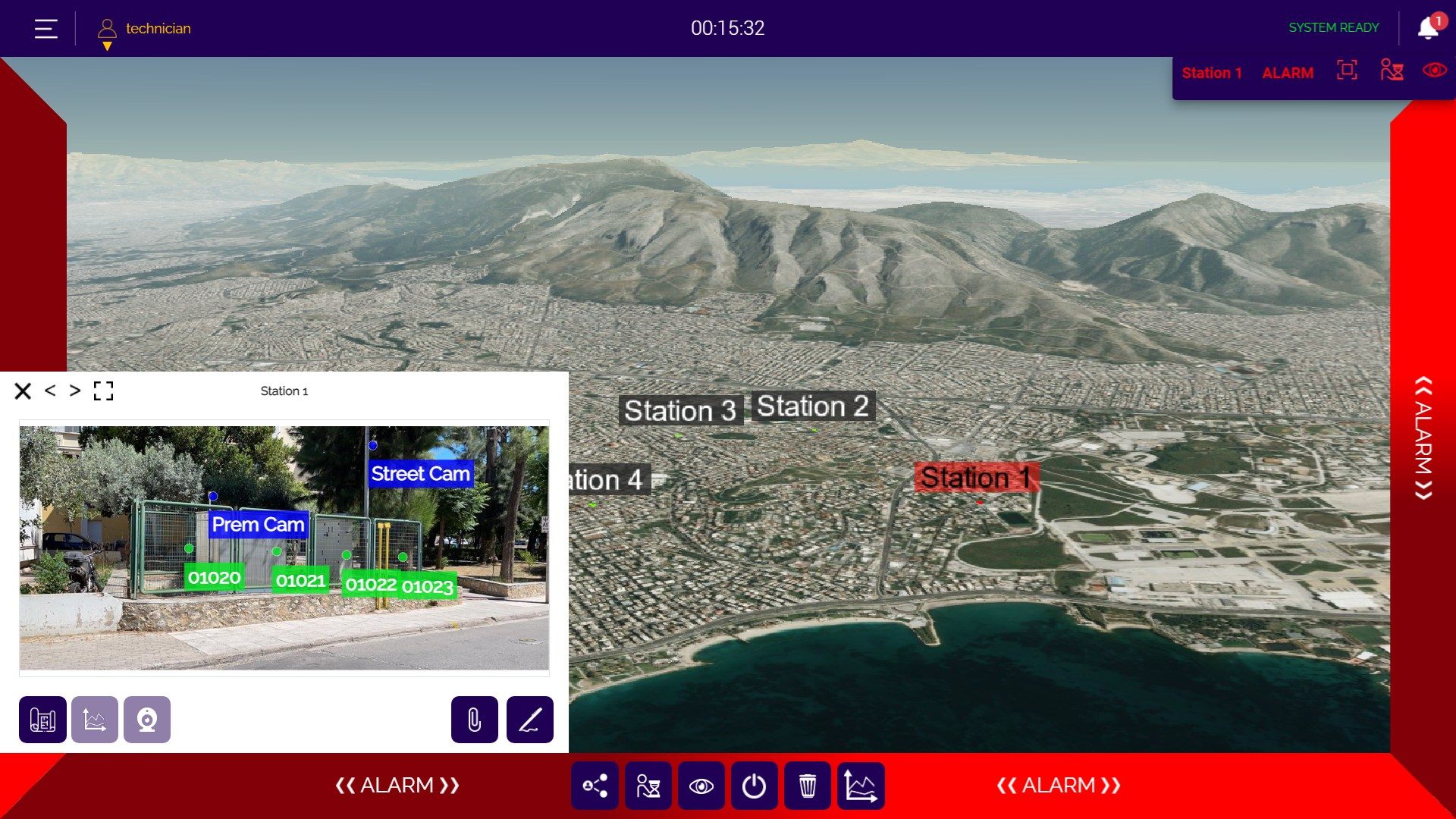
D-Command Control screen in alarm state: red alarm frame, 3D city map with the site's stations, and a pop-up showing the fence at Station 1 with its sensor IDs and cameras

Stop losing alarms between separate systems.

D-Command Control is the D-FENCE command-and-control platform. It places every sensor zone, camera and gate of your site on a detailed 3D map. When a sensor alarms, the zone turns red, the camera that covers it opens beside the map, and the operator can assign the event to the team member closest to the scene. The alert reaches the screen in < 3 s.

01

One picture, not ten screens

Sensors, cameras and alarms from every system meet on one geolocated map.

02

Respond in seconds

The alert arrives in < 3 s, with the right camera already open.

03

Fits what you run

Dry contact, RS232 / RS485, IP and a secured API: plug and play with your PSIM, VMS or SCADA.

Behind the screen is a palm-size, fan-less gateway. One gateway takes up to 16 sensor controllers of up to 16 sensors each, IP cameras, and a dry-contact controller with up to 64 inputs and 60 outputs. Up to 13 sites connect over fibre-optic lines to one main control centre.

D-Command Control is open by design. Alarms leave over dry contacts, RS232 / RS485 or IP, and a secured API connects it to the PSIM, VMS, BMS, SCADA or access-control system you already run. It can be your main screen or a feed into the one you have.

From the first touch to the right response.

  1. Sensor

    A D-FENCE sensor detects force on the barrier and reports its zone.

  2. Controller

    Up to 16 sensors per sensor controller, chained on RS485.

  3. Gateway

    Up to 16 controllers, IP cameras and dry contacts per gateway.

  4. D-Command Control

    The zone turns red on the 3D map and its camera opens, in < 3 s.

  5. Response

    The nearest team is tasked, sirens and lights switch on, and your PSIM / VMS receives the event.

Seen in full.

Every image opens full size. Product sheets are shown whole, exactly as D-FENCE publishes them.

Specifications & documents.

SpecificationsD-Command Control
Alert time
< 3 s
Display
Web-based 3D GIS map; desktop, laptop or mobile
Sensor controllers per gateway
up to 16
Sensors per sensor controller
up to 16
Dry-contact controller
up to 64 inputs / 60 outputs
Multi-site
up to 13 sites over fibre-optic lines
Field interfaces
RS232, RS485, IP, dry contact (N.O. / N.C.)
Integration
Secured API; REST / SOAP / SNMP / PSIM bridge; ONVIF cameras
Connects to
PSIM, VMS, BMS, SCADA, access control, fire alarm, radar, LPR
Gateway dimensions / weight
112 × 84 × 25 mm, 450 g
Gateway enclosure
Aluminium, passive fan-less cooling; wall / VESA / DIN mount (optional)
Operating temperature
−40 °C to 80 °C
MTTF
> 200,000 h
Power
AC 110–240 V, 50–60 Hz (transformer included) or 10–36 V DC
Gateway ports
2 × 100 Mbps Ethernet (RJ45), 4 × USB 2.0, 1 × RS232, 1 × HDMI (up to 1920 × 1080 @ 60 Hz)
Wireless
Wi-Fi / Bluetooth / cellular removed for security; added on demand
Compliance
FCC / CE, RoHS-II

Specification text, ready for your tender.

Copy it into your specification. It describes the system by what it must do, so any alternative has to meet every point.

D-Command ControlTender specification textDatasheet
  1. General

    The system shall be D-Command Control by D-FENCE Electronic Fencing and Security Systems Ltd. (ISO 9001:2015 certified quality management), or an approved equivalent that meets every requirement in this section.

  2. Function

    Every sensor, camera and alarm on one geolocated map, in the control room or on a phone.
  3. The system shall provide

    • 3D synoptic map: Sites, zones, cameras and sensors on a detailed 3D GIS view, on desktop, laptop or phone.
    • Camera on alarm: The alarm opens the camera that covers the zone, with PTZ control in the same window.
    • Sensor-level readings: Live values per sensor show exactly which one raised the alarm.
    • Task the right person: Assign the event to the team member closest to the scene and keep the record for debriefing.
    • Automatic response: Sirens, floodlights, PA and local outputs switched through relays when the alarm arrives.
    • Multi-site: Up to 13 sites linked over fibre-optic lines to one main control centre.
    • Open, secured API: REST / SOAP / SNMP bridges into PSIM, VMS, BMS, SCADA and access control.
  4. Technical requirements

    • Alert time: < 3 s
    • Display: Web-based 3D GIS map; desktop, laptop or mobile
    • Sensor controllers per gateway: up to 16
    • Sensors per sensor controller: up to 16
    • Dry-contact controller: up to 64 inputs / 60 outputs
    • Multi-site: up to 13 sites over fibre-optic lines
    • Field interfaces: RS232, RS485, IP, dry contact (N.O. / N.C.)
    • Integration: Secured API; REST / SOAP / SNMP / PSIM bridge; ONVIF cameras
    • Connects to: PSIM, VMS, BMS, SCADA, access control, fire alarm, radar, LPR
    • Gateway dimensions / weight: 112 × 84 × 25 mm, 450 g
    • Gateway enclosure: Aluminium, passive fan-less cooling; wall / VESA / DIN mount (optional)
    • Operating temperature: −40 °C to 80 °C
    • MTTF: > 200,000 h
    • Power: AC 110–240 V, 50–60 Hz (transformer included) or 10–36 V DC
    • Gateway ports: 2 × 100 Mbps Ethernet (RJ45), 4 × USB 2.0, 1 × RS232, 1 × HDMI (up to 1920 × 1080 @ 60 Hz)
    • Wireless: Wi-Fi / Bluetooth / cellular removed for security; added on demand
    • Compliance: FCC / CE, RoHS-II
  5. Detection sequence

    1. Sensor: A D-FENCE sensor detects force on the barrier and reports its zone.
    2. Controller: Up to 16 sensors per sensor controller, chained on RS485.
    3. Gateway: Up to 16 controllers, IP cameras and dry contacts per gateway.
    4. D-Command Control: The zone turns red on the 3D map and its camera opens, in < 3 s.
    5. Response: The nearest team is tasked, sirens and lights switch on, and your PSIM / VMS receives the event.
  6. Submittals

    Before installation, the contractor shall submit the manufacturer's datasheet, the installation instructions and the zone layout for approval.

Discuss your project.

Tell us the site, the threat and the line. D-FENCE engineers will propose the right barrier, sensor and platform, ready for your integrator.
Build the full line.